Course Learning Objectives:
-
Recognize the circumstances that have precipitated the popularity of EIFS with drainage,
-
Define the basic components of EIFS with drainage,
-
Consider the benefits and limitations of EIFS with drainage,
-
Assess the code changes that have a bearing on EIFS specifications,
-
Consider the types of EIFS with drainage available.
Definitions used in this lesson:
- provides a secondary weather barrier to protect the sheathing behind the
system,
- provides a drainage plane between the insulation board and the structural
substrate weather barrier,
- provides a vented termination at the bottom of the system to allow moisture
infiltration within and behind the EIF System to exit the wall.
Let's look at these three components in more detail.First, a primary wall barrier of any occupied facility is intended to control most of the weather from invading the assembly of wall materials. Then, a secondary weather barrier is used. It can be comprised of various products including a moisture shedding material:
The traditional 60 minute Grade D building paper (one layer is enough according to ICBO codes).
Building paper products that are placed over the structural wall sheathing, with or without effective weather resistance:
- many asphalt and felt based building papers are not weather resistant,
- spun-bonded polyolefin sheets are both tear and weather resistant.
- they are still competitive with other cladding options,
- the insulation value of the system is maintained, and
- the same low maintenance exterior finishes are still used.
- They also allow the drainage of incidental moisture that could possibly damage the substrate.
- a secondary barrier behind a drainable EIFS, or
- a standard system installed with special inspections at all phases of
application, or
- system termination or penetration details tested in a full scale water penetration test to determine performance.
-
A weather barrier of building paper,
-
mechanically attached and grooved EPS,
vented track at bottom terminations.
To evaluate and apply the principles of a drainable EIF System and a non-drainable EIF System. Explanations offer the building science principles involved, suitable substrates, and options available to address small versus larger construction projects.
At the end of this program, the participants will be able to:
EIFS: Exterior Insulation Finish System
Vapor Retarder (sometimes incorrectly referred to as vapor barrier): A component or a combination of components that stop the movement of moisture through a building enclosure assembly.
Air Barrier: A component or a combination of components that stop the movement of air through a building enclosure assembly.
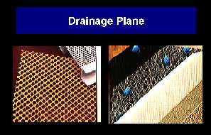
Drainage Plane: A deliberate positioning of cut channels or openings where moisture can travel by gravity to a predetermined outlet.
EPS: Expanded polystyrene (insulation board).
Weather Barrier: A wall or roof assembly designed to eliminate weather intrusion to a building interior.
Course:
EIF Systems have been used with success in the US for over 30 years. Today they represent about 20% of all exterior wall cladding used in new commercial construction, and a total of approximately 320 million square feet. in 1998. EIF Systems are especially popular for their design flexibility combined with insulation and weather stopping properties.
EIF Systems are not only used extensively by design professionals in new construction, but are becoming increasingly popular in the rehabilitation of older existing buildings.
Several years ago, a localized crisis occurred in Wilmington North Carolina, where a number of houses with EIFS showed problems of water intrusion between the insulation board and the wall substrate sheathing, causing the sheathing to biodegrade and decay. Similar degradation of substrate has occurred elsewhere, and the cause has been attributed to moisture leakage at poorly sealed wall openings around windows and doors.
Although the problem in North Carolina was strictly residential, it was heavily publicized in the commercial sector.
Over 80% of the water intrusion was caused by windows that leaked and did not meet minimum code requirements; lack of proper flashing and detailing at roof to wall intersections; improper attachments of decking to walls; and absence or failure of sealant joints at dissimilar product to product junctions and terminations.
One other factor which contributed to damage done to the substrates hidden behind EIF Systems, was the State of North Carolina requirement for a vapor retarder on the inside of the exterior walls of a house. Due to the climatic conditions in Wilmington NC, this is the wrong location for a vapor retarder, and in the case of water intrusion, this vapor retarder prevented the wall materials from drying. It was shown in this instance that homes without the vapor retarder sustained little or no damage when compared to homes that had a vapor retarder.
Let's look at how a drainable EIF System differs from the conventional barrier type Exterior Insulation and Finish System.
EIFS with internal drainage, adds three desirable attributes to EIFS systems:
Trowel applied synthetic membrane products typically used over weather
resistant gypsum based sheathing can be effective
Glass fiber mat gypsum sheathing (such as Georgia-Pacific DensGlass Gold)
- except in BOCA dominated jurisdictions. DensGlass Gold as a sheathing
surface alone, is not recognized as a weather barrier.
Also very important to the weather barrier are the window and door head
flashings. As these openings, when improperly sealed, are a major cause
of water infiltration, the flashing re-directs infiltrated water to the
exterior.
For an EIF System internal drainage plane to be effective, several options are offered. They include a separate component, often plastic, in the form of a lath or a mat - flat board insulation is then mechanically attached over it. In some instances, the insulation board is adhesively attached to the mat,
Experiences indicate:
Lath may buckle after attachment over the weather barrier and create an
uneven surface for the attachment of the EPS insulation board.
A plastic mat or lath adds an extra layer to the assembly which affects
the thickness of the completed assembly.
Both solutions require an additional installation step.
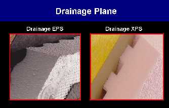
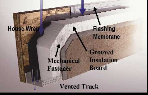
Another method of achieving a drainage plane is by means of grooves or channels which are factory cut on the back of the insulation board. This option is offered with EPS as well as with XPS (extruded polystyrene), produced by at the manufacturers of each type.
There are several different designs for the grooves, from curved to square, but the main criteria is that the grooves always aline to provide a continuous vertical drainage channel no matter how the boards are installed.
As you can see from this discussion, the design of the drainage channels
offers provisions for drainage of the water, even when the insulation boards
aren't aligned.
The addition of a drainable type EIF System creates specific detailing conditions that will be different from the standard barrier type EIF System.
Flashings through the EIF System may be used for multi-story buildings,
so that incidental moisture that gets behind the EIF System does not have
to drain all the way down before it can get out.
How many stories can moisture be effectively drained before a horizontal
through flashing with drainage is installed? The answer to this depends
on several factors, such as:
the number of penetrations in the wall which permits the egress of moisture,
potential damage to organic substrates if moisture is not removed quickly,
irregularities in the vertical flush plane of the wall which may interfere
with drainage.
Typically, in a multi-storey building, the design of the structure will
dictate how often the system must be drained. In most cases, drainage provisions
are made every 2 to 5 floors.
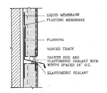
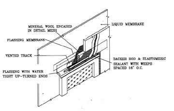
Wall penetrations such as at a window head or a door head must provide an
opportunity for the moisture to exit the system.

Here the system terminates in the drainage track, which is above the opening
head flashing. At the outer edge of the flashing, a backer rod and sealant
are installed over the wall opening head flashing with weep holes placed
16 inches on center - to permit collected drainage from the internal system
drainage tracks, to drain over the flashing and through the sealant weep
holes.
A secondary weather resistive barrier is placed continuous at both horizontal and vertical expansion joints.
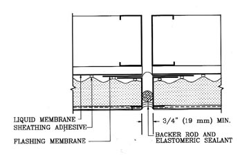
Horizontal joints may have a flashing to allow moisture to exit at the joint.
If a backer rod and sealant joint is present, then weep holes through the
sealant joint are required.
In a drainage EIF System, the drainage plane behind the EPS (either drainage mat or grooves) can cause a chimney effect during a fire. This effect can produce results in a standard large-scale fire test which would prevent the system from passing the test.
To solve this problem, a strip of mineral wool insulation is placed at the termination of the system, above any penetration or object which could allow fire to enter the system from below. The mineral wool can be considered a fire safing material to minimize or eliminate the chimney effect. Since the mineral wool allows water to passively drain through it, the drainage plane is not exposed to the potential fire conditions - and drainage capabilities are not compromised.
This step does not have to be performed in combustible type construction
such as Type V or Type VI.
A penetration flashing must allow for the moisture to exit above the penetration, and also protect the system from fire exposure below.
A window head flashing is used to divert water from the head of the window or door opening, and the EIF System is terminated by a drainage track. A backer rod and sealant joint is installed between the drainage track and head flashing. Weep holes are installed in the rod/sealant joint at 16 inches on center.
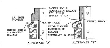
In a cladding transition, incidental moisture behind the cladding should be drained out at this location via flashing and weep holes. However, if the lower cladding system is appropriately designed for drainage, and sufficient protection is provided for the interior wall cavity, then it may be possible to allow the moisture to continue to drain behind the subsequent cladding.
Drainage at a transition can be done by either of the two methods shown. The preferred is Alternate "B" which diverts the moisture away from the system at the transition and thus does not rely on the drainability of the other cladding system.
The need for a decorative band in Alternate "A" is optional.
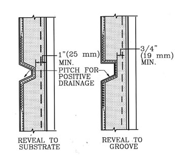
The addition of a drainable type EIF System creates specific detailing conditions
that will be different from the standard barrier type EIF System when considering
EPS thickness for cutting reveals in the surface.
Aesthetic reveals must be cut so that there is a minimum of 1 inch (25 mm) of EPS board left between the bottom of the reveal and the substrate. Thus, there will be 3/4 inch (19 mm) between the bottom of the reveal and the drainage channel
The attachment of the system is always a critical part and available options
are determined by the type of secondary weather barrier that is selected.
Over building paper, house wrap or a peel and stick bituminous membrane,
an insulation board must be mechanically fastened.
Note that the limited negative wind load resistance as measured with standard
1.0 lb/cu ft drainage EPS at 1.5 inch (38 mm) thick.
Using a trowel applied secondary weather resistive barrier allows for an option of adhesively attaching the insulation board. The foam insulation compatible adhesive attachment, offers significant negative windload resistance.
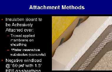
Substrates that are not water sensitive, such as concrete or masonry, may
or may not incorporate a secondary weather resistive barrier, but the insulation
board should be adhesively attached using the appropriate compatible adhesive.
The remaining components of EIFSystem with drainage, are the drainage track end outlets. These exterior polyvinyl terminations have been used successfully in Parex systems for many years.

The vented tracks have perforations at the bottom for the drainage of moisture,
and the small size reduces the likelihood of insect intrusion.
The front flanges of the track have an extra row of perforations that are designed for better keying of the base coat and mesh.
Back-wrapping the base termination can be performed, but if special care is not taken, the back-wrapping can block the drainage plane and prevent proper flow of moisture.
Let's look at some of benefits that a drainable system can provide along with some of the limitations that are associated with this type of system.
EIFS with drainage provides the same benefits as standard EIFS - design flexibility. Despite costs that are slightly higher than barrier type systems:
Although these systems are designed for drainage, they are not designed to cope with larger quantities of moisture that may exfiltrate from a building interior such as in cooler climates. These systems also provide for an additional layer of rain shedding protection for the structure.
The limitations of these systems are also similar to that of barrier EIFS. In addition, the minimal insulation thickness is 1-1/2 inches compared to 3/4 inch for standard systems. The minimum slope on non-vertical surfaces is 1 to 2 or 27 degrees. Lightness or reflectance values of a darker colored finish must be at least 30% to avoid the possibility of damage to the EPS due to temperature extremes. Also, the deflection criteria of L/240 for the substrate of a drainable EIF System are the same as for a barrier system.
Some of the limitations that may be unique to drainage EIF Systems include the minimum thickness of the EPS board. In most barrier systems, the minimum thickness of the EPS is 3/4” (19 mm), but in drainage systems, the minimum thickness of the insulation board is 1-1/2” (38 mm). As most drainable systems are mechanically attached, the additional thickness is needed in order to achieve negative wind load values that are realistic, and to accommodate the depth of the channels in a grooved drainage insulation board.
Thermal bridging of the fasteners in a mechanically attached drainage system will cause temperature differences on the surface of the EIF System, and this may lead to a fastener “read through” problem during certain atmospheric conditions. Another possible limitation is the system termination above windows, doors and other overhead conditions. The system must be able to drain at these locations, and the provisions for allowing this drainage could be an aesthetic issue.
Note that the drainage feature does not eliminate the need for proper design and installation of the enclosure assembly.
An EIFS drainage system warranty typically covers the same items as does the warranty on a barrier EIF System. A warranty issued on an EIF System usually covers defects in the components manufactured or installed by the EIFS manufacturer, which comprise the system.
On occasion, an EIFS manufacturer will include any labor which is used to replace any material or component that is proven to be materially defective.
In addition to the standard warranty on materials and possibly labor, the EIFS manufacturer may also provide a warranty or statement that the drainage system will perform to allow incidental moisture to escape.
Keep in mind that drainable EIF Systems are designed to cope with incidental moisture and not large volumes of water, and are not intended to replace good construction technology practices, nor to compensate for other building components that do not function as designed or intended.
Let's take a look at the current status of some model building codes and how much significance they place on drainable EIF Systems.
The Southern Code hasn't made any change in regard to EIFS. However, North Carolina and Georgia now require a drainage system for wood frame construction.
Note: Some cities like Greensborough NC, require drainage for all construction with EIFS.
SBCCI, Georgia, and North Carolina have also amended their codes to prevent foam plastic insulation from continuing down to grade. This is primarily due to pest control.
The BOCA code is still working on a final position, but to date, they require one of the following options for all frame construction:
Details that pass the water penetration test at specified conditions will become part of an Evaluation Report, signed by a design professional and can be used in a not drainable EIF System without special inspections.
No drainage is required for concrete or masonry substrates.
ICBO is also still working on a final position, but currently they require the use of a secondary barrier - in the form of building paper or liquid membrane, behind the system for all Type V construction (wood frame or sheathing).
An update to the status of ICBO. Recent changes were adopted to limit Type V construction that would require a secondary weather resistive barrier to R-1 and R-3 - which are basically wood frame construction in which people live (have a bed), but light commercial (like offices or retail) are not included. Also, there is a standard for drainage efficiency.
With all of the various design considerations, a variety of components available, code restrictions, requirements of the project, and desires of the design professional and building owner, there are a number of options open in the choice of a drainage EIF System. Let's look at a few of the criteria that might be used in making the proper selection for a drainage system.
A first major determining factor in deciding the type of drainage system that would be appropriate is the type of building on which the system is to be applied.
Residential and light commercial normally (due to economics) often use combustible construction, so the components that go into the system are not as restrictive. Items such as fire testing and wind loading is not as crucial from the perspective of restrictive codes.
Large commercial projects are typically of non-combustible construction. For non-combustible construction, fire testing of the system and their components, is far more critical, and the code reports are more specific about what can be used, so the use of some components of the system may be prohibited.
High traffic areas mandate that the system and its' components be able to take the abuse of weather, resist damage, and still perform as a drainable EIF System.
High rise versus low rise - decisions on attachment methods, fastening patterns, and weather barrier choices, will be affected by the height of the building.
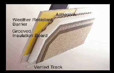
For smaller projects such as residential and light commercial, a mechanically attached drainage EIF System is appropriate, as wind load requirements are generally not restrictive. Types of components and fire testing are not as critical, so in most cases system, costs can be minimized.
Here's an example of a drainage EIF System for residential and light commercial, and the components that would go into it.
In large commercial, high-rise, and institutional type buildings, the codes are more restrictive in these types of buildings. Fire and structural testing of the systems and the components are often required. The use of certain components may be required and the use of others may be limited or not allowed.
Wind and suction loads are more important, especially in high-rise construction, so adhesive attachment becomes the preferred method as invariably provides for the greater negative wind (suction) load values.
In this example, note the ribbons of adhesive placed vertically on part of the grooved EPS board that will be in contact with the secondary weather barrier. In this type of application, care must be taken to avoid applying adhesive in the grooves of the EPS board and blocking drainage capabilities.
An alternate approach to a fully drainable EIF System would be one that
is part way between a standard (non-drainable) barrier system and a drainable
one.
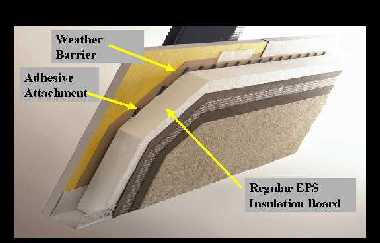
This halfway approach uses flat a EPS board that is adhesively attached
with the ribbons of adhesive placed vertically over a secondary weather
resistive barrier. Although this would not be considered a drainable EIF
System, the spaces between two ribbons of adhesive provide some drainage
capabilities and offer less likelihood of trapping moisture behind the
system.
Note the similarities to the full drainable system.
When a drainage efficiency test is standardized for submission to code organizations and all EIF Systems are measured for their drain-ability in the same manner, this type of system can be evaluated to determine how efficiently it performs.
For institutional and high traffic locations, a high impact and puncture resistant substrate and cladding should be used. The EIF Systems that provide the best impact and puncture resistance are the thick base coat or flexible PM systems. These systems provide the strength that is desired, and eliminate the need for all of the joints that are required in a standard PM system, and they do this at a reasonable cost.
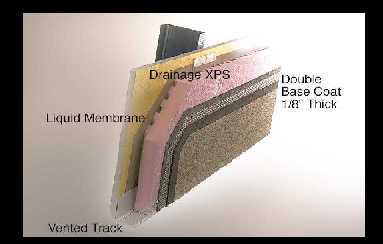
A thick base coat drainage system will provide the best resistance to
impact and puncture resistance in high traffic areas.
This assembly incorporates a secondary weather resistive barrier that may be a conventional building paper, a peel and stick membrane, or a liquid applied material. The grooved extruded polystyrene (XPS) is mechanically attached to the frame with appropriate fasteners and plates using a pattern to meet anticipated wind/suction loads.
The base coat contains a self graded aggregate to ensure additional thickness, and an appropriate reinforcing mesh is embedded in the first base coat layer to achieve specified impact and puncture resistance.
A second layer of base coat is applied so that overall base coat thickness is 1/8 inch (3.2 mm), and then a primer and finish is applied in the conventional EIFS manner.
In high rise construction, there are some issues that must be addressed if a drainable type EIF System is used in place of a conventional Class PB EIF System.
A drainable system must be able to resist the higher wind loads that occur in high rise construction, so the appropriate weather resistive barrier must be used for the adhesive attachment of the EPS board. The use of supplemental mechanical attachment is not necessary with the appropriate adhesive attachment, but may be used if desired.
If mechanically attached XPS is used, a fastening pattern must be sufficient to meet anticipated wind loads with a safety factor prescribed by prevailing codes. The substrate must also be designed to handle anticipated wind loads with the necessary safety factor.
There are no current requirements for drainage frequency or efficiency in EIFS assemblies. Depending on building design, height, and penetrations, drainage could be accomplished perhaps every floor in cooler climates and every second floor in warmer climates, in high rise construction.
A drainable EIF System must meet the requirements for non-combustible construction and have code approval for this type of installation.
In order to receive code approval, the system must have been tested in either the UBC Multi-story Fire Tests 26-4 or 26-9, and have written documentation to this effect.
Generally this type of construction requires a fire resistive assembly, so the system must demonstrate that the installation of a drainable EIF System does not alter the fire resistive rating of the substrate.
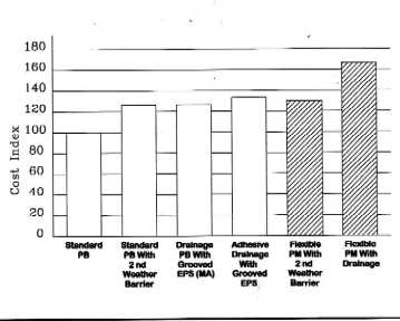
Cost for the drainable EIF System will be of significant importance in
making the decision on which one to use. This chart compares the various
drainable systems available, with the cost of installing a standard Class
PB EIF System.
One approach, which is economical, is to use standard flat EPS board that is adhesively attached to a trowel applied secondary weather resistive membrane. The ribbons of adhesive should be oriented vertically to provide an opportunity to drain. This type of system will be approximately 25% more than the standard Class PB.
A mechanically attached grooved EPS system over building paper will also cost about 25% above standard Class PB, and an adhesively attached grooved EPS over trowel applied secondary weather barrier will be 30% to 40% over the standard system.
High impact/puncture resistant systems, mechanically attached over a building paper weather barrier without the grooved XPS will have a cost premium of approximately 30% to 40%. A thick base coat system incorporating the grooved XPS will carry a cost premium of about 60% over the standard Class PB System.
Most of the building codes in use today are adopting requirements for drainage efficiency in a drainable EIF System. To get code compliance, these systems must have been tested in a manner that can measure the drainage efficiency of the system.
Currently the industry group, EIMA (EIFS Industry Members Association) has proposed a modified ASTM E-331 test to measure the drainage efficiency, and to establish the amount of water retained by the system after a 48-hour period.
The EIMA test:
for drainage efficiency is EIMA 200.02, and
for water retention is EIMA 200.03.
At present, the pass/fail criteria are still being established, but this
is a measure of the performance of the drainable EIF System and should
be part of the designer's specifications.
Choose a drainage system that originates from one manufacturer for assurance that all of the components are designed to work together and are compatible with one another.
Using a system from one manufacturer ensures that the system and the components have all been tested for the requirements of the various code organizations. The code reports contain reference to all of the system, its components, the tests that have been performed, and the limitations on the installation of the system.
A "single source" supply enables one manufacturer to warrant the system and all of its' components.
Summary:
In conclusion, there are many new systems available to answer the water intrusion concern, so design options are not limited. However, it is important to optimize a choice and not over-engineer the assembly or construction. The key to a successful installation is the proper and rationale selection of a quality system is:
proper detailing of the system, and
a strong and effective specification.
End of Course: